The Ball Grid Array, or BGA bundle is not the unique protect of huge, advanced chips on laptop motherboards: at the moment even easy microcontrollers can be found with these little solder balls. Nonetheless, many hobbyists choose to stick with QFP and QFN packages as a result of they’re simpler to solder. Whereas that may be a honest level, BGA packages can supply vital house financial savings, and are generally the one selection: with the continuing chip scarcity, another bundle variations would possibly merely be unavailable. Even soldering doesn’t need to be difficult: when you’re already snug with solder paste and reflow profiles, including a BGA or two into the combo is fairly simple.
On this article we’ll present that working with BGA chips isn’t as tough as it might appear. The main target can be on printed circuit board design: how to attract correct footprints, methods to route plenty of indicators and what capabilities your PCB producer ought to have. We’ll cowl soldering and rework methods in a future article, however first let’s check out why BGAs are used in any respect.
What’s All This Ball-Grid Stuff, Anyhow?
As laptop expertise superior within the Nineties, the motherboards inside our PCs grew to become increasingly more advanced. The 8-bit knowledge buses from the Eighties gave option to 16-bit, 32-bit and even 64-bit broad buses between the CPU, the principle reminiscence and enlargement playing cards like onerous disk controllers and show adapters. These buses all needed to be carried into and out of assorted chips, which due to this fact wanted plenty of pins.
The everyday bundle for advanced chips on the time was the quad-flat-package (QFP), with lengthy rows of gull-wing formed pins on both sides. When scaled as much as a pin depend of 200 or extra, these packages grew to become more and more unwieldy: not solely did they change into very massive in comparison with the chip inside, the pins additionally grew to become extraordinarily small and fragile. Giant QFP chips required cautious dealing with to keep away from bending any pins and making the chip unsolderable.
The Ball Grid Array bundle, or BGA, was developed to unravel each of those issues. Inserting the pins in a grid on the backside of the bundle, as an alternative of spreading them across the edge, makes for a much more area-efficient design. As well as, solder balls are way more strong than the tiny little pins on small-pitch QFP packages. Though producers initially feared manufacturing and testing points, the BGA bundle turned out to be very dependable and has since change into ubiquitous in all varieties of digital gear.
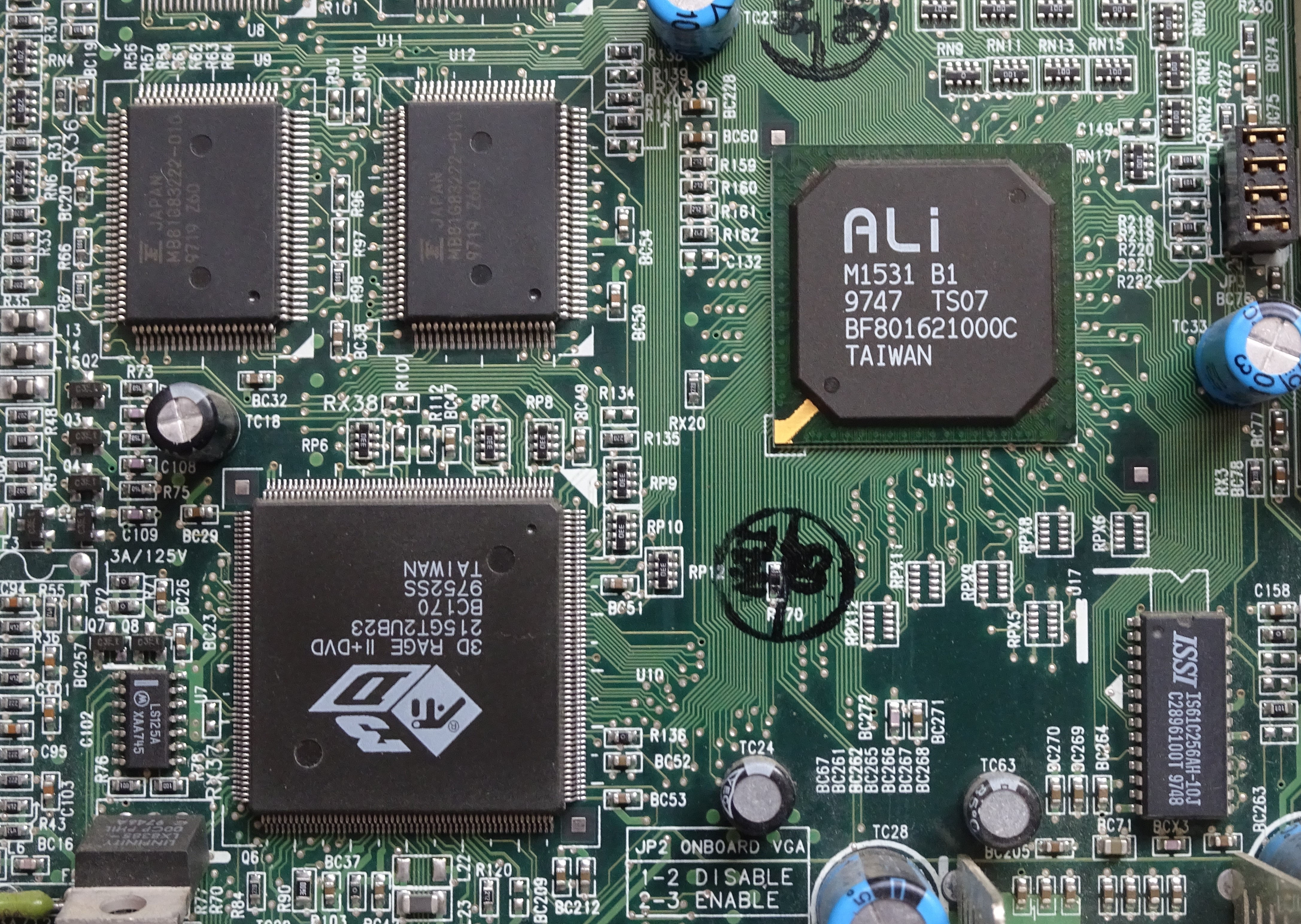
The image beneath, exhibiting a part of a 1997 classic PC motherboard, clearly illustrates the distinction in space effectivity between a QFP and a BGA bundle. The ATI VGA controller on the left has a 208 pin QFP bundle with a 0.5 mm pin pitch. The Ali M1531 system controller, on the appropriate, manages to suit 328 pins on its BGA bundle, with solder balls at a way more snug 1.27 mm pitch.
A BGA bundle is often constructed round an interposer: a small printed circuit board that serves as an interface between the precise chip and the circuit board onto which it’s mounted. The chip is wire-bonded to the interposer and lined in protecting epoxy. The interposer routes the indicators from the sting of the chip to an array of pads on the underside, onto which little balls of solder are hooked up. The finished BGA bundle is then positioned onto the printed circuit board and heated. The solder balls soften and create a connection between the board and the interposer.
Typical BGAs within the early days had a ball pitch of 1.27 mm. As expertise improved, BGA packages grew to become smaller and smaller, till the interposer was not a lot bigger than the chip inside. These miniaturized BGAs are often known as chip-scale packages, or CSPs, and usually have a ball pitch between 1.0 and 0.5 mm.
The search for miniaturization didn’t finish there nevertheless: semiconductor producers ultimately developed the flip-chip BGA, or wafer-level chip scale bundle (WL-CSP), that disbursed with the interposer altogether. As an alternative, flip chip designs place the solder balls instantly onto the chip’s floor, with a pitch that may be as small as 0.3 mm. The chip is then mounted upside-down onto the circuit board, both with a protecting layer of epoxy on its again or with no packaging in any respect.
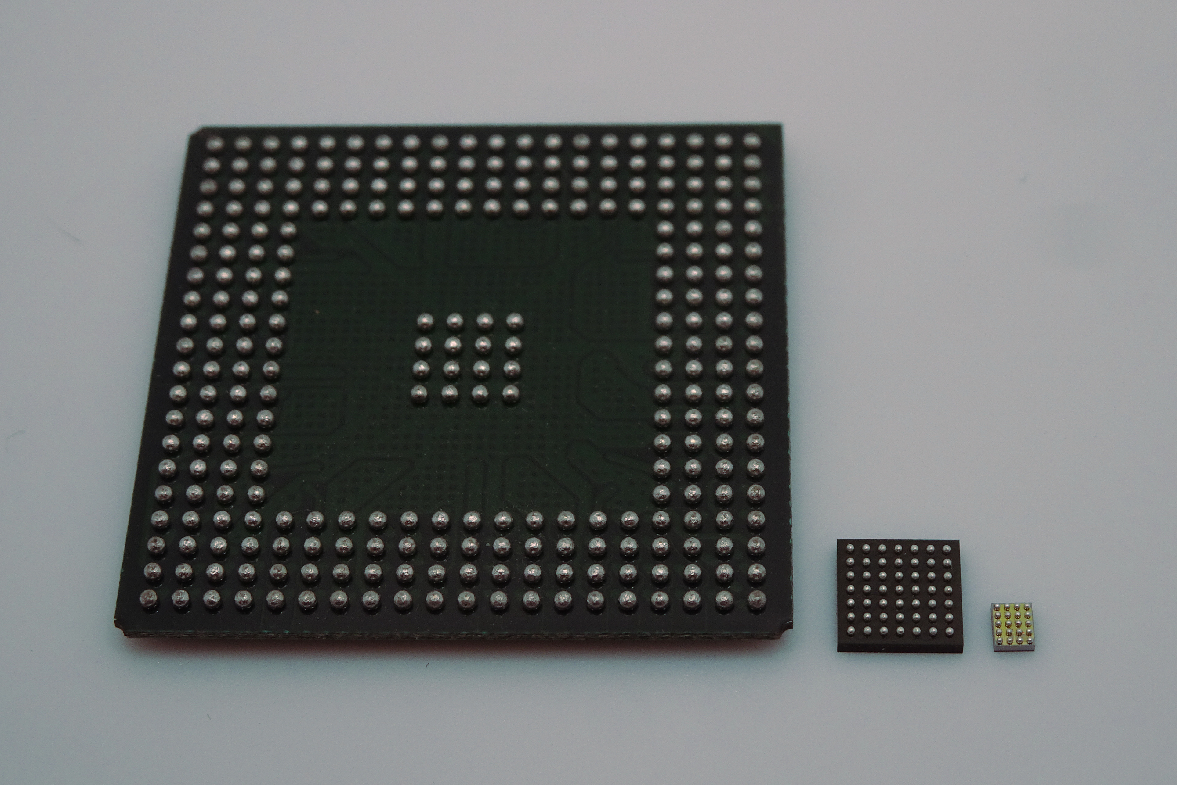
There’s an enormous number of advertising names for various BGA-type packages, with little standardization between producers. However when you merely wish to use a BGA chip, it doesn’t actually matter what it’s known as and even the way it was made: the PCB structure methods are the identical for all sorts. So let’s take a look at methods to design PCB layouts for them.
BGA Fundamentals: Pads and Footprints
Image the next situation: you’re designing a state-of-the artwork LIDAR setup, and also you’ve chosen TI’s TDC7201 time-to-digital converter to carry out time-of-flight measurements. In contrast to its predecessor the TDC7200, this chip is just out there in a 25-pin nFBGA bundle, so you don’t have any selection however to make a BGA board. You additionally want a microcontroller to do some knowledge processing and determine on a Microchip ATmega164. Sadly, at the moment’s chip scarcity signifies that the QFP and QFN variations are nowhere to be discovered, so you find yourself caught with the 49-pin VFBGA model. As for the LDO regulator to energy the entire thing, you come across an excellent discount: your favourite provider has ONSemi’s NCP161 on sale. As you’ll have guessed, that one additionally is available in a BGA bundle, a tiny four-pin model on this case.
So how do you go about designing a PCB for this trio of BGA chips? As all the time, the producers’ datasheets are an excellent place to begin. Let’s first take a look at what ON Semiconductor says about how to attract the correct footprint for his or her NCP161: on web page 21 of the datasheet we discover the really helpful land sample that specifies a 0.15 mm pad diameter with NSMD sort pads.
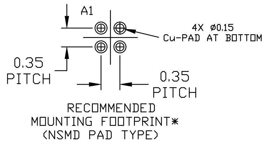
NSMD stands for “Non-Solder Masks Outlined”, which refers to a solder pad that’s not partially lined by the solder masks. The opposite possibility is a Solder Masks Outlined pad, through which the solder masks does cowl a part of the pad. Whereas each varieties have their functions, the NSMD sort is normally really helpful in producers’ datasheets for BGA chips as a result of it permits a extra strong solder connection: the solder ball can grip the edges of the pad in addition to the highest.
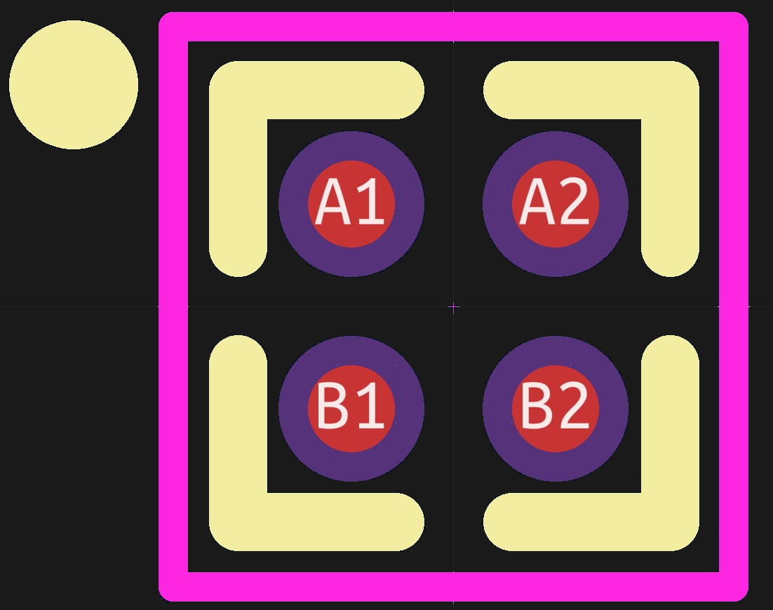
If we draw a footprint for our little four-pin BGA bundle in KiCAD, the 2 choices look as follows. The copper pads are proven in purple, with the solder masks openings in purple. The pink define is the element’s courtyard, which determines how shut different parts could also be mounted.
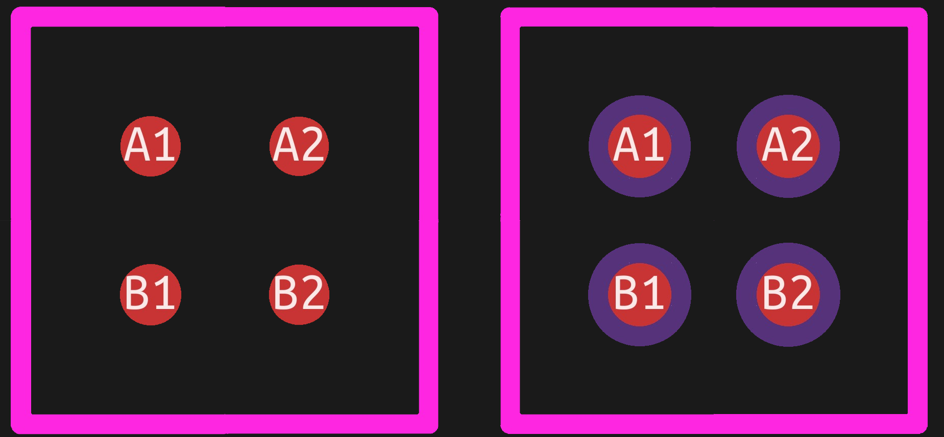
For the NSMD model, the solder masks openings ought to be barely bigger than the copper pads; on this case, we’ve used 0.25 mm openings on 0.15 mm pads, which suggests the solder masks openings lengthen simply 0.05 mm on both facet of the pad. It’s best to test along with your PCB producer if their solder masks alignment is correct sufficient to do that; a typical values is 2 mils (0.05 mm), which signifies that within the worst case, your solder masks will nearly contact the sting of your pad. In case your producer can not present extra correct alignment, you would possibly wish to enlarge the solder pad opening a bit of bit extra. Understand that the remaining solder masks between the pads ought to then nonetheless fulfill the minimal solder masks sliver rule.
Observe that the pads of BGAs usually are not numbered sequentially, however in a row-column format: the rows are labelled A, B, C and so forth from prime to backside, whereas the columns are numbered from left to proper. Pin A1, within the top-left nook, is generally indicated by some mark on the highest facet of the chip that can assist you orient the half accurately.
One factor that can be of nice assist when assembling your PCB, particularly when you’re doing it manually, is having the bundle define indicated in your silkscreen layer. Since you may’t see the solder balls and the pads once you’re putting the chip, the silkscreen is the one option to inform when you’ve positioned your chip accurately. Don’t overlook to attract some type of indicator to level out which pin is A1, in any other case you’ll nonetheless find yourself guessing which of the 4 orientations is appropriate.
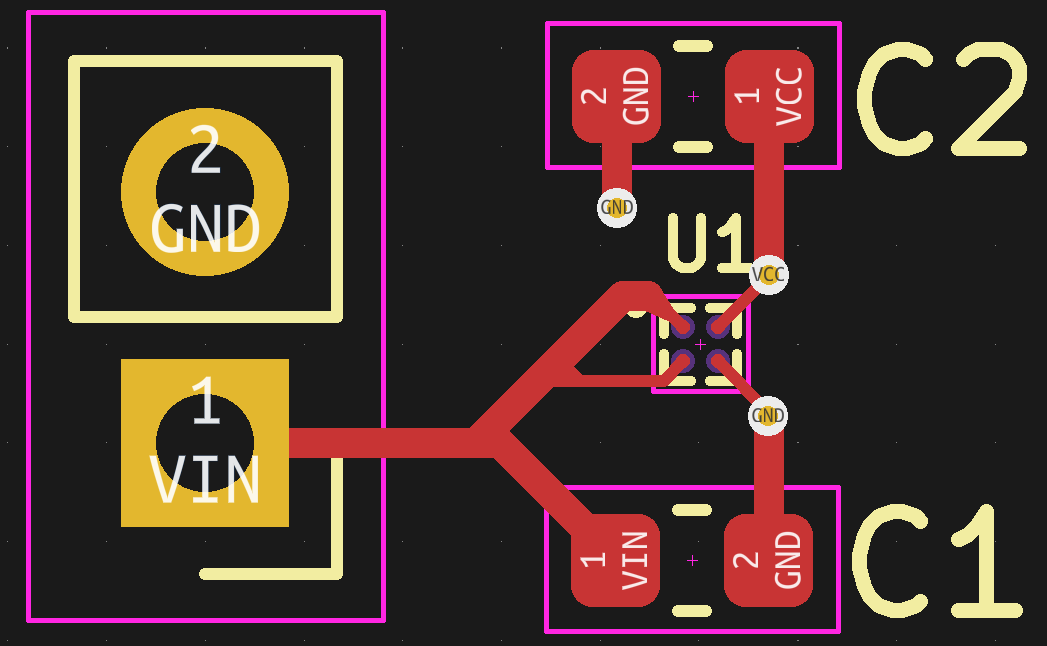
With simply 4 pads, hooking up this voltage regulator chip to the remainder of our circuit is simple. Whereas it is likely to be tempting to attract a couple of large energy planes for the enter, output and floor connections and overlap them with the pads, it’s normally higher to attract a skinny hint to every pad first, then join that hint to any bigger constructions.
The explanation for that is solderability. When the solder ball melts, it is going to attempt to adhere to any copper it might see, which suggests each the solder pad and the hint connecting to it. The chip will due to this fact expertise a slight pull within the path of the hint throughout soldering. Making the connections radially symmetric ought to cancel out the forces exerted by every solder ball and guarantee a extra predictable soldering course of.
BGA Routing: Canine-Bone Format
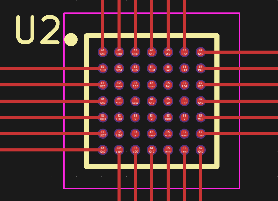
Issues get a bit extra difficult after we place our microcontroller, with its 7×7 grid of solder balls. Routing traces to all 49 pads isn’t so easy, so let’s begin with the best bit: the outer pins. We will merely route them outward utilizing horizontal and vertical traces.
The second layer of pins will be routed with tracks going between the outer pads. In fact, our PCB design guidelines ought to permit this: the minimal hint width and clearance ought to be not more than c = (p-d)/3, the place p is the pad pitch and d is the pad diameter. For this instance, with a 0.65 mm pitch and 0.35 mm diameter, the minimal clearance and observe width comes all the way down to 0.1 mm: tight, however nonetheless potential at many producers.
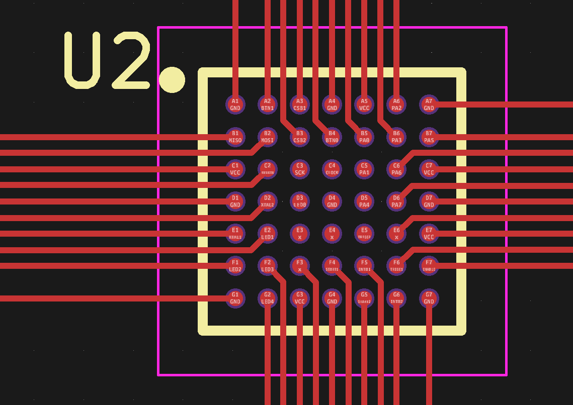
From the third layer inwards it will get extra fascinating, as a result of from this level on we’ll want vias to get our indicators out. The most typical approach of doing that is to put one by way of in the course of each 4 pads and route a diagonal hint to it from one of many pads.
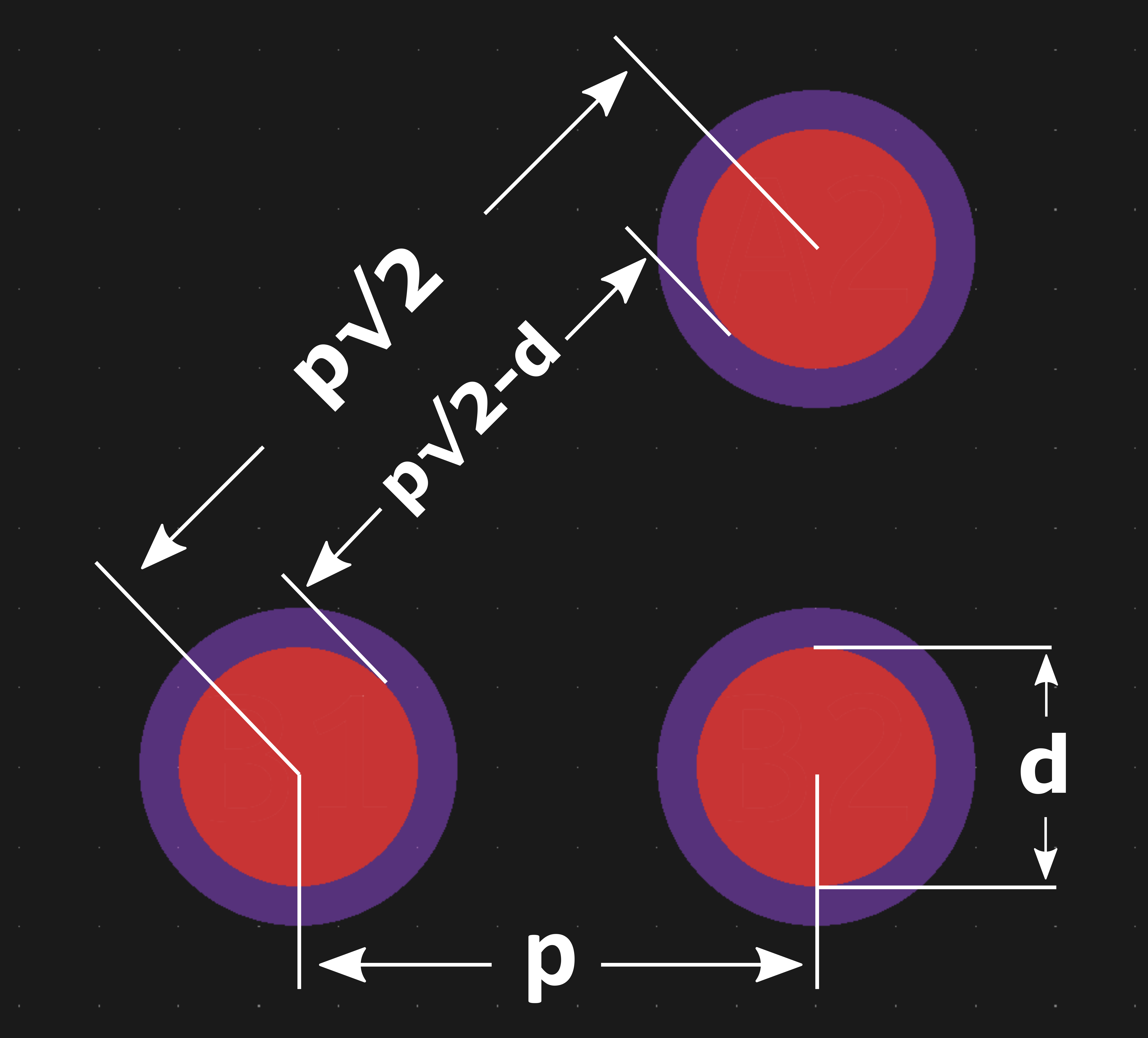
In fact, we must always first make it possible for we’ve sufficient house to place down a by way of in any respect. A bit of geometry tells us precisely how a lot we want: if the pad pitch is p, then the diagonal distance between the middle factors of two pads is p√2. The space between the interior edges of the pads is then p√2 – d, the place d is the pad diameter.
For the ATmega164, with p = 0.65 mm and d = 0.35 mm, this implies we’ve 0.57 mm of house between the pads. We have to depart at the very least 0.1 mm of clearance between the pads and the by way of, so our most by way of dimension is 0.37 mm. That is just about on the restrict of what most producers can ship; you may achieve a bit of little bit of room by shifting the by way of barely nearer to the pad it’s related to, however for smaller-pitch components like this one you’ll need to go for the costlier manufacturing choices.
After putting the vias we find yourself with the structure proven beneath. That is the dog-bone structure fashion, named for the pad-trace-via mixture that type of seems to be like a cartoonish bone. On this easy case we solely have 9 dog-bones and loads of house to route the indicators on the underside layer. If we had an 8×8 ball bundle as an alternative, then we’d have sixteen dog-bones and the underside layer can be simply as crowded as the highest layer.
The dog-bone structure fashion will be prolonged to any BGA dimension. However because the variety of pads grows, the variety of layers wanted to route all of the indicators will increase as properly. A 7×7 or 8×8 BGA will be routed with simply two sign layers, however a 9×9 or 10×10 chip wants at the very least three. Typically, you want a brand new routing layer for each two extra rows of pads. In observe, most of the indicators can be provide and floor pins that may instantly hook up with an inner energy aircraft and don’t want additional routing. There may be unused pins, which once more provides you a bit extra routing house.
It’s necessary to make sure that all vias below your BGA chip are tented, or lined in solder masks. In the event that they’re not, then the molten solder balls may movement onto the vias in addition to the meant solder pads, inflicting misalignment and shorts. You’ll need to test along with your PCB producer in the event that they assist tented vias: this usually requires an extra processing step through which the by way of holes are crammed with some materials earlier than the solder masks is utilized.
BGA Routing: By way of-in-Pad Format
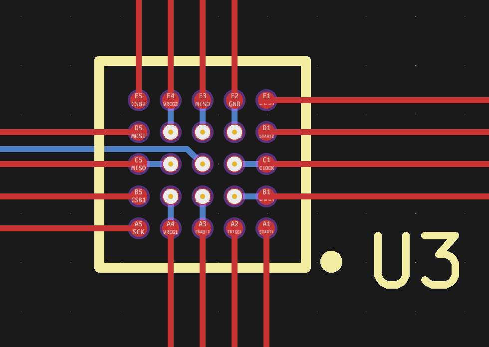
One other structure fashion for routing BGAs is via-in-pad. That is usually executed for very fantastic pitch BGAs the place you may’t match a by way of between 4 pads. The fundamental thought is easy: you place one by way of inside every of the interior pads and route the indicators outward from a decrease layer. The issue is that you may’t merely place regular vias in your BGA pads, as a result of the molten solder can be sucked contained in the by way of gap by capillary motion and trigger unreliable joints. Your producer will due to this fact must fill the vias and apply a metallic overlaying on prime to make sure a flat, solderable floor. The official time period for that is an IPC-4761 Sort VII, Crammed and Capped by way of.
The by way of holes must be sufficiently small to suit contained in the BGA pad, and can normally find yourself being microvias: drilled by a laser relatively than a mechanical drill. You can even simplify your routing through the use of blind vias, which don’t go right through the board however cease the place you need them to. That is usually a pricey possibility, but when your design makes use of the smallest Sort VII microvias and the tightest clearance, then you definately’re in all probability already utilizing the costliest plan that features blind vias anyway. Beneath is an instance structure exhibiting the via-in-pad approach utilized to the TDC7201, though we wouldn’t usually want this on such a easy 25-pin system.
Whether or not you used the dog-bone or via-in-pad structure kinds, when you’ve managed to convey all indicators to the sting of your BGA (a course of known as “escape routing”) the remainder of your PCB design can be nearly as when you’d used a QFP or QFN bundle. The ultimate outcome would possibly look just like the picture proven on the prime of this text.
As you may see, designing PCBs for small-to-medium sized BGA packages doesn’t need to be difficult. So long as the minimal hint pitch, clearance and by way of dimension supplied by your PCB producer are a very good match for the pad dimension and pitch of the chips you’re planning to make use of, you’re all set. Basic BGAs with a 1.27 mm pitch can be doable at nearly any producer, whereas smaller chip-size packages with a pitch all the way down to 0.65 mm usually want one of many extra superior processing choices with tighter design guidelines.
The smallest wafer-level packages, with a ball pitch of 0.5 mm or smaller, can solely be processed on probably the most superior manufacturing traces. If you end up attempting to design a PCB for such a small chip, it is likely to be worthwhile to proceed in search of that QFN or QFP model, as a result of there’s little level in changing an unobtainium chip with an unmanufacturable PCB.


